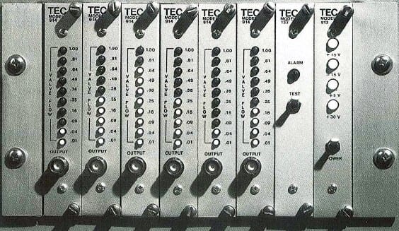
TEC MODEL 1414:
SAFETY & RELIEF VALVE MONITORING

Acoustic Valve Flow Indication System
Acoustic monitoring of safety and relief valves in nuclear power plants provides reliable indication of flow through the valves so that the operator knows when there is a path open for loss of coolant. This method of valve surveillance satisfies the requirements of NRC Regulatory Guide 1.197 (Dec. 1980) and can be easily implemented using the TEC Acoustic Valve Flow Indication System.
For each valve, a high temperature accelerometer is connected to a TEC Model 504 Charge Converter, which is designed to continue operating under accident conditions. The output of the charge converter is routed by cable to a TEC Model 914 Valve Flow Monitor module. The 914 module, which contains a built-in current source for powering the remote charge converter, performs signal processing and displays ten levels of flow indication. It also provides digital outputs corresponding to a user-defined lower trip level, an alarm level and an upper trip level.
The system is provided in both standard 19” wide racks, containing up to sixteen channels and six channels, respectively. Each system contains power module(s) and alarm module(s). All input and output connections are made at terminal lugs on the rear of the rack. Each 914 module has a front panel BNC connector for auxiliary access to the analog signal.
TEC’s QA/QC program meets the requirements of 10CFR Part 50, Appendix B, and 10CFR Part 21. For environmental and seismic qualification specific to this product, go to the Model 1414’s Qualification page.
The TEC Model 1414 has been environmentally and seismically qualified by type testing to IEEE 323-1974, Standard for Qualifying Class 1E Equipment for Nuclear Power Generating Stations and IEEE 344-1975, Recommended Practice for Seismic Qualification of Class 1E Equipment for Nuclear Power Generating Stations. The system is manufactured by TEC under its Nuclear Quality Assurance Program in accordance with ANSI N45.2. The system is qualified as documented in TEC Test Report No. 517-TR-03 AND 517-TR-10.
The configuration for the Model 1414-7-(4) system (a typical three-channel system) consists of up to three monitoring channels per rack. Each channel consists of a field-mounted sensor and preamplifier. Signal processing electronics are located in the control room cabinet. A standard 19-inch rack-mountable system also is available.
The field-mounted equipment consists of an Endevco Accelerometer, qualified for nuclear service, as the sensor, with a TEC Model 504 Charge Converter as the sensor preamplifier, serving each of the sensor sites in-line between the accelerometer and control room equipment. For environmental protection, the 504 may be installed in the TEC Model 106-2 transient shields in groups of up to three (3) charge converters per transient shield.
The signal is then rerouted to the control room signal processing equipment mounted in the Model 1414-7-(4) Rack. From the Model 504, the signal travels directly to the Model 914-2 Valve Flow Monitoring Module. The Model 914-2 conditions and processes the signal, and displays and distributes any signal causing an alarm indication. The Model 133C Alarm Modules provide single-channel alarm functions.
Voltage Gain Any integer, 1-100, selectable on TEC model 914 board
Bandwidth -3dB points: 15kHz, 50 kHz (min.)
Signal Output 51 ohm, current drive +/- 20 mA
RMS Converter Gain 0.5-1.0, adjustable
Bar Graph Operates on RMS output, 10 steps each 200mV
Power Required 117 V ac, 60 Hz (1 A max.)

